
Hydraulic Catwalk on a Space-Limited Deck: Fit, Lift and Retrofit
A power catwalk is usually discussed as a question of force: how much pipe it can lift, how fast it cycles, whether the drive is electric or hydraulic. On a deck with room to spare, that is the right conversation. On a platform, a jack-up or a crowded older pad, the first question is different — whether the machine can physically get there, turn around, and hand pipe to the drill floor without closing the only route the crew uses to walk off.
The transport envelope is where most space-limited projects are won or lost. A whole unit built for a land rig travels at roughly 16.8 to 17.5 metres long and 32 to 35 tonnes on the host frame. A split configuration brings the longest piece under 12.5 metres. That single number decides which crane, which vessel, which gate and which laydown area you are planning around — long before anyone argues about cycle time.
This guide is about the physical fit: six measurements to take before a quotation, how the transport envelope interacts with crane capacity, how floor-height tiers map onto real decks, what the ramp interface demands of an existing rig, and the checks that should happen before the first joint goes up.
What Space-Limited Actually Means: Six Measurements
Space is not one number. On an offshore or congested site, the constraint shows up in six places, and any one of them can rule out a configuration that looks fine on a datasheet.
**Laydown and staging area.** The unit needs room to receive pipe, stage three joints at a time, and let the carrier leave. Measure the clear rectangle, not the painted boundary.
**Crane capacity at radius.** Not the headline SWL. The number that matters is what the deck crane can pick at the radius where the module will actually be set down, with the sea state and list you expect on the day.
**Access route.** Door widths, hatch openings, pipe racks and cable trays along the path. A 12.5-metre module still has to reach the installation point.
**Floor height and setback geometry.** The vertical distance from deck to drill floor, plus where the setback sits and how much room the ramp has to land.
**Escape and muster routes.** The machine must not become the only way in or out of the drill floor. Regulators and rig managers care about this more than suppliers usually expect.
**Utilities.** Power availability, hazardous-area classification around the install point, and where hydraulic and control lines can be routed without crossing walkways.
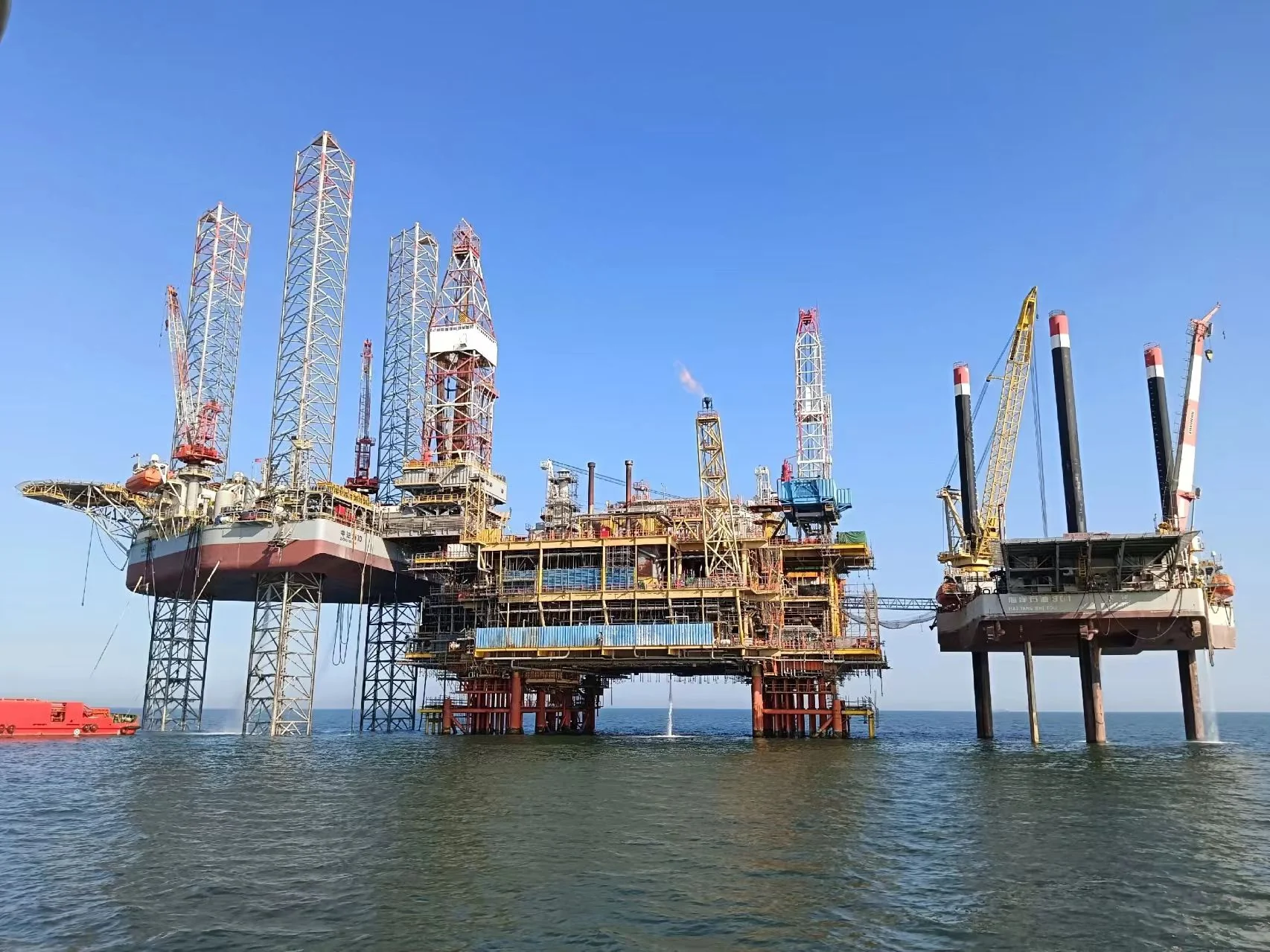
Figure 1 — A production platform deck: process modules, flare boom and a jack-up working alongside. Space on this deck is won or lost between the modules, not on the drawing board.
Write those six numbers down before you ask for a drawing. Every one of them feeds a different part of the design, and a supplier who does not ask for them is quoting a catalogue item rather than a fit.
The Transport Envelope Decides the Logistics
Two configurations exist for the same machine, and the difference is not cosmetic. A whole unit ships as one frame; a split unit ships as two or three modules that assemble on site. The split version costs more to build and takes longer to assemble, but it changes which crane and which route are available to you — and on a platform, that is often the difference between a project and a cancelled project.
| Item | Whole transport | Split transport | Why it matters |
|---|---|---|---|
| Overall length | 16,800–17,500 mm | under 12,500 mm | Route width, vessel deck, hatch openings |
| Host frame weight | 32,000–35,000 kg | divided across modules | Crane capacity at the working radius |
| Assembly on site | None | Bolted and pinned joints | Deck time, lifting plan, crew hours |
| Best fit | Land rigs, wide pads | Platforms, congested pads, retrofit | Decides the whole logistics chain |
If the split option is the one that fits, budget it properly. The five cost factors behind a catwalk budget are assembly time, lifting, transport, deck work and commissioning — rarely the frame alone.
The trade is straightforward: split transport buys access and pays for it in assembly time and lifting complexity. If the crane can only pick 12 tonnes at the required radius, a 35-tonne whole unit is not an option regardless of how good the machine is. Work backwards from the crane, not forwards from the product.
Pipe length sets a floor under the envelope. The unit handles joints up to 13.5 metres, which is what range 3 pipe looks like on most rigs. That length, plus the ramp, is why the whole-transport figure sits where it does and why splitting is not a marketing option.
Matching the Unit to the Floor Height
Catwalks are tiered by drill floor height, not by pipe size. The five production tiers span 7.5 to 14 metres, and each tier carries its own cycle time and installed power because the lift geometry changes as the floor goes up.
| Tier | Floor height (m) | Cycle time per joint | System power |
|---|---|---|---|
| Small | 7.5–8 | under 80 s | 105 kW |
| Small-medium | 9.5–10 | under 90 s | 105 kW |
| Medium | 10.5–11 | under 100 s | 105 kW |
| Large | 12–12.5 | under 115 s | 120 kW |
| Very large | 13.76–14 | under 130 s | 120 kW |
The error to avoid is treating floor height as an approximate match. A unit sized for a 10-metre floor does not simply work on a 12-metre floor with a longer ramp; the lift angle, the support geometry and the pipe trajectory all change. On a platform, where the drill floor often sits higher relative to a cramped deck, this is the most common mismatch in early specifications.
If your floor height falls between tiers, take the next tier up and confirm the ramp interface. Under-sizing shows up later as slow cycles and jammed joints, both of which cost more than the step up in frame size.
Pipe Range and What It Does to the Layout
One machine covers a wide pipe range, and that range is what makes a single unit viable on a platform where a second machine would never fit.
| Parameter | Value | Layout consequence |
|---|---|---|
| Max joint length | 13.5 m | Sets envelope and ramp length |
| Casing | up to 24 in | Widest item the trough must carry |
| Drill collar | up to 11 in | V-groove and stop geometry |
| Max transport load | 45 kN | Deck and support reaction check |
| Drill pipe | 2-7/8 to 5-7/8 in, 3 joints per cycle | Cycle planning and staging area |
| Control reach | 50 m wireless remote | Operator can stand clear of the path |
For a reference point on sustained pipe volumes at the other end of the scale, our 8,882 m ultra-deep well case shows the same handling principle carried to full depth.
The 45 kN transport load is worth flagging early with the deck engineer. On a platform, the reaction point is the deck plate and its framing, not a purpose-built foundation, and the load path has to be justified. Get the reaction figures into the structural conversation before the layout is frozen.
Hydraulic Drive in Tight Quarters
Where space is the constraint, hydraulic drive has practical advantages that have nothing to do with torque curves. The direct-push variant lifts with oil cylinders, uses a load-sensing system, and reads position through a displacement sensor that adjusts speed automatically. That means fewer electrical cabinets on deck, a power pack that can be placed away from the drill floor, and motion that is easy to limit when the machine is working inside a tight footprint.
The trade-off is real too. Hydraulic systems need hose routing, oil cooling and a disciplined leak-management regime, and hose runs have to be planned around walkways rather than across them. Electric drive removes the hoses but adds cabinets, VFD panels and cable routing, which on a congested deck can be the harder problem. The comparison between the two drive types is covered separately in our guide to VFD versus hydraulic catwalk drives; the point here is that on a space-limited site, the deciding factor is usually where the power and control hardware can physically live.
Automation is the other direction of travel on the same deck. Our guide to the road to an unmanned drill floor sets out which functions come next and what the deck has to support before they arrive.
Hazardous-area classification is part of that decision. The control cabinets and remote on our units are built to ExdIIBT4, with three control locations — wireless remote, local panel and drillers cabin — so the operator is not forced to stand in the machine’s working envelope. On a platform, that last point is often what gets approval.
The Ramp Interface: Where Retrofits Succeed or Fail
The ramp is the part of a retrofit that decides whether the project fits the existing rig or fights it. Our ramp is built as an H-beam weldment with a double-line electric winch and pulley set, and its upper end pins to the rig’s existing setback ear plates at the same dimensions as the original ramp. In practice that means the machine can replace a conventional ramp rather than demand a new one — which is the single biggest cost and schedule saver on a retrofit.
**Pin geometry first.** Confirm the ear plate hole diameter, spacing and height on the existing setback before design freeze. These three numbers cannot be adjusted on site.
**Deck load path.** Four hydraulic legs with 1,070 mm ground clearance carry the frame. Check the deck framing under each leg, not just the plate thickness.
**Rear interface.** A 5-tonne air winch mounting position and a 1.5-inch air line connection are provisioned at the rear of the base, which is where most rigs want the utility tie-in.
**Cable and hose routes.** Plan the run from the power pack to the frame along existing cable trays. Do not cross the walkway at deck level.
**Setback clearance.** Confirm the machine’s raised position clears the setback and the travelling block path through the full cycle, not just at rest.
If the rig already has a working catwalk and the goal is automation rather than replacement, the retrofit path is different again — our guide to retrofitting existing rigs covers that case, including what can be reused.
Lifting, Installation Window and Sequence
Onshore, installation is a crane day. Offshore, it is a weather-dependent operation that has to be planned against a vessel schedule, a lifting plan and a permit set. Three things shorten that window more than anything else: a lifting plan built around the actual crane chart rather than the rated capacity, modules that assemble with pins and bolts rather than welding, and a commissioning sequence that can start before the last module is landed.
The practical order is: set the base frame and confirm leg loads, land the ramp and pin to the setback, install the pipe-handling frame, tie in power and control, then run dry cycles without pipe. Dry cycles catch most geometry problems, and they are the cheapest test available. Only after dry cycles should the first joint be run, and only with the driller and the deck supervisor watching the same reference points.
Two planning notes that come up repeatedly. First, the split configuration needs a staging area for modules that is often larger than the footprint of the assembled machine — check that early. Second, the vessel’s crane and the platform crane rarely have the same capacity at the same radius; plan the lift for the weaker of the two.
Commissioning Checks Before the First Joint
The checks below are the ones that catch problems while they are still cheap. They assume dry cycles have been completed.
Confirm all four leg pressures are within the commissioned range with the frame loaded.
Verify emergency lowering returns the frame to the horizontal position with power removed.
Test the winch over-torque stop at the set point, not just at trip.
Confirm the auto stop-pin engages and holds a joint against the trough.
Run the remote from the far end of its 50 m range, then from behind the setback.
Check both single-step and automatic modes cycle without fault.
Verify the drillers cabin control mirrors the local panel state.
Confirm hazardous-area sealing on cabinets and quick-disconnects after assembly.
Check hose and cable runs clear of walkways through the full cycle.
Confirm the raised position clears the setback and block path.
Record cycle time against the tier figure with the actual pipe on the actual rig.
Hand over the fault log, the setting sheets and the spare-parts list at the same time as the machine.
When a Catwalk Is the Wrong Answer
A catwalk solves pipe handling between the rack and the drill floor. It does not solve a deck that is too small for any frame at all, and in those cases the honest answer is a different machine. On platforms where even a split unit cannot be staged, the work is often better served by a drill floor manipulator, a pipe-handling arm or a setback-based system, each of which trades throughput for footprint.
The same applies where pipe volumes are low and irregular. A catwalk earns its place by cycling consistently; on a workover with a handful of joints a day, a crane and a crew may genuinely be cheaper. We would rather say that at the quotation stage than discover it during commissioning — our selection guide sets out the operating conditions where each approach makes sense.
Technical Data Sheet
| Parameter | Specification |
|---|---|
| Floor height tiers | 7.5–8 / 9.5–10 / 10.5–11 / 12–12.5 / 13.76–14 m |
| Max joint length | 13.5 m |
| Pipe range | Casing up to 24 in; drill collar up to 11 in; drill pipe 2-7/8 to 5-7/8 in |
| Joints per cycle | 3 (drill pipe mode) |
| Max transport load | 45 kN |
| Cycle time | under 80 s (small tier) to under 130 s (very large tier) |
| Installed power | 105 kW / 120 kW by tier |
| Transport | Whole 16,800–17,500 mm; split under 12,500 mm; host frame 32,000–35,000 kg |
| Deck interface | 4 hydraulic legs, 1,070 mm ground clearance; ramp pins to existing setback ear plates |
| Control | Wireless remote 50 m, local panel, drillers cabin; cabinets ExdIIBT4 |
Figures are from the manufacturer’s product documentation for the units we supply; site-specific engineering, deck reinforcement and lifting plans remain project deliverables.
Frequently Asked Questions
Can a hydraulic catwalk be installed on an existing platform without replacing the ramp?
A: In most cases yes, because the ramp is built to match the rig’s original ramp dimensions and pins to the existing setback ear plates. The three numbers that must be confirmed before design freeze are the ear plate hole diameter, the hole spacing and the height above the drill floor. If those match, the ramp interfaces directly; if they do not, an adapter is a design task rather than a site improvisation.
What is the minimum deck area needed for a split-transport unit?
A: Budget for two areas, not one. The assembled footprint is the smaller of the two; the staging area for modules during assembly is usually larger, and it has to be reachable by the crane at a workable radius. As a starting point, plan the staging rectangle from the longest module at under 12,500 mm plus handling clearance, and confirm the crane can reach every module position without re-rigging.
How does floor height affect the choice between tiers?
A: Floor height drives the lift geometry, which drives the tier, which drives cycle time and installed power. The five tiers cover 7.5 to 14 metres, with cycle times from under 80 seconds to under 130 seconds per joint. If the deck sits between tiers, take the next tier up: under-sizing shows up later as slow cycles and pipe handling faults rather than as an obvious failure.
Is hydraulic drive better than electric on a space-limited deck?
A: It depends on where the hardware can live, not on which drive is technically superior. Hydraulic drive moves the power pack away from the machine and needs hose routing; electric drive removes the hoses but adds cabinets, VFD panels and cable runs. On a congested deck the deciding factor is usually the space available for control hardware and the route for cables or hoses, not the drive type itself.
What deck load should be planned for?
A: The transport load is rated at 45 kN, and the frame transfers it through four hydraulic legs with 1,070 mm ground clearance. The number that matters for structural approval is the reaction at each leg under the worst combination of pipe load and lift position, which is a project-specific calculation. Get those reactions to the deck engineer before the layout is frozen.
How long does installation take offshore?
A: Installation time is dominated by the lifting window rather than by assembly. Pin-and-bolt modules assemble faster than welded frames, and commissioning can begin before the last module lands. The sequence is base frame and leg loads, ramp and setback pins, pipe-handling frame, power and control tie-in, then dry cycles before the first joint. Weather and vessel schedule, not the machine, usually set the duration.
Next Step: Send the Deck Measurements
Speak directly with an engineer: [email protected] | WhatsApp on request.
→ Send your deck measurements — six numbers and a crane chart are enough for a first configuration.
→ See the pipe-handling range — floor-height tiers, pipe range and transport options.
→ Read a multi-site deployment — the same machine across very different yards.
→ Talk to an engineer — if the deck is tight, say so first; that is where the design starts.
References
[1] American Petroleum Institute — standards for drilling and well servicing equipment. https://www.api.org
[2] International Association of Drilling Contractors — rig floor safety guidance. https://www.iadc.org
[3] International Organization for Standardization — machinery and equipment standards. https://www.iso.org
Need help choosing the right equipment?
Our engineers review your application and recommend the best fit — no obligation.